Let’s continue with D3D10 introduction. In the first part we have seen togheter what D3D10 is and their pourpose, a little bit of story and some examples. Now we will incentre our forces on rendering, the passes to create the image on the screen.
Rendering
The rendering pipeline is showed below:
With some variables each vertex is positioned in his final position on the screen. This operation is called projection and it’s executed in vertex shader. Beyond this other values are computed that will be given to the pixel shader (vertex color, for example). The projection happens in 3 passages called “space changes”
The object position is called Object Space
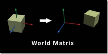
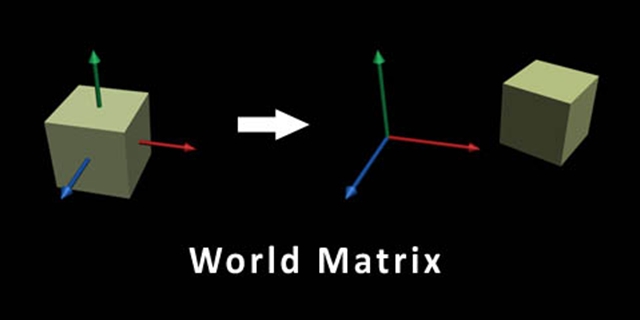
With first trasformation the object is positioned in a particolar point with its rotation and scaling (for example the cube it’s created with the centre in 0,0,0, but in the scene must be in 30,40,50 and rotated by 45 degrees on Y axes).
This position is called World Space
The mesh is not yer visibile becouse another parameter it’ needed: from which place are we looking it?
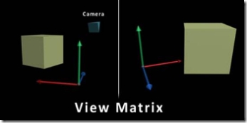
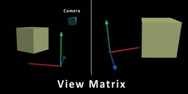
The second trasformation defines the camera: the point from which we look the object. Let’s imagine a film-set. The actor is in a particoular point on the scene and there are some cameras that look at him creating different images.
The 3Dobject will change again coordinates: in this mode it will be positioned in center in comparison to camera direction and at right distance.
This new position is called View Space
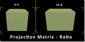
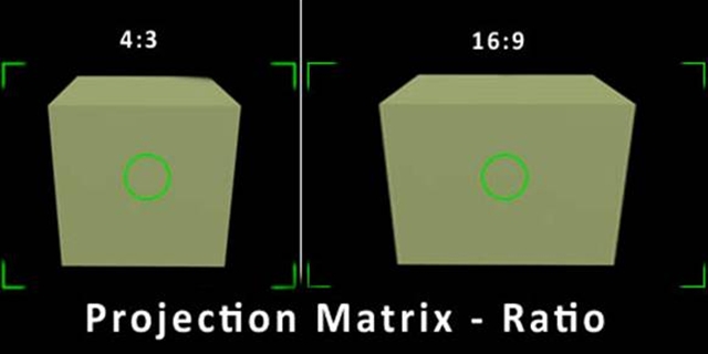
Last phase could be summarized with a proposition: “How much i look?”. Last phase infact set the visible camera anche. Last trasformation will convert coordinates in Projection Space and will set all visible object’s coordinates in a range betweeb -1 and +1 (for Z from 0 to 1)
All scene will be visibile in this gap.
The vertex shader does really this operations: given the position, the camera and the projection-type, it move the object from his initial position to his last object in the -1 +1 gap, called homogeneous space.
All these operation for each scene vertex, numbers that with our videocard surpass the miliard of elaboration for each second.
The next operation it’s managed automatically. Positioned all triangles, and discarded these ones that are not visibles, they are filled. Fill it’s an operation, that for each pixel, writes color point that will create the final image on the screen. This operation is called rastering.
The process counts the reading of 3 vertices from the triangle that rapresent limits. In his inner it’s computed the middle weight of each values of a pixel. Let’s do an example.
Immagine that in a struct, beyond the position, there are also numeric values called T.
The 3 vertices that we are processing have got T values = at 3,6 and 15. The rastering will start to elaborate all pixel and compute the average. In the trigangle center T will be = to 3+6+15/3 = 8. Each time that we go near the start vertex, T will have a value near his original value (for example the pixel at hal from center and original pixel will have got T = 9).
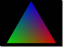
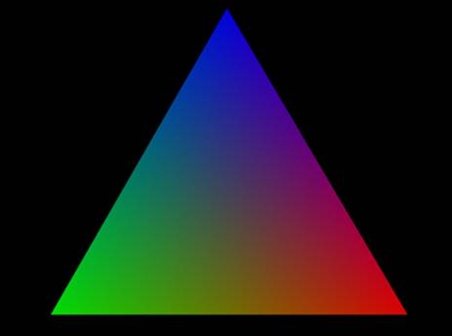
Each vertex has a own color that is interpolated.
This values, computed as a middle weight, will be passed to Pixel Shader.
The pixel shader receives the struct generated by vertex with new values equal to 3 vertices’middle weight in this pixel
Starting from this values the pixel shader will compute the pixel’s final color, giving it to usa as a struct formed by 4 numbers (generally an array float, with a 0,1 range, rapresenting the RGB color struct and pixel trasparency (alpha))
Finally, the color will be compared with the actual color already on the screen, and with the settings’ help, pixel shader could overwrite, leave or blend the color with the previous one
This value will be the exact that will splash on the screen
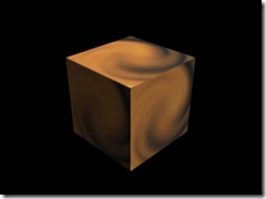
Final result:
Math
Transformation informations (from object to projection space) are stored as matrices, number grids which in DirectX are squared (4x4)
Translations, rotations, cameras‘ position are computer simply by multipling rows per columns between position vector and our matrix.
The vertex position it’s managed as 4 floats (XYZ and W). W it’ called the homogeneous coordinate and its value is 1 (value setted by DirectX, then you have not to manage it). The scope of W number it’s only numerical, becouse the only mode it’s the only mode to build a translaction with a product vector x matrix (you could verify numerically but the argument will be better elaborated in next tutorials)
If you have some doubles about matrix i suggest you take a look in some books or search with google.
The pixel final position it’s the product between original position vector, world, view and projection matrix.
Final Position = Vector x World x View x Transform
Or also using the associative property
Final Position = Vector x Transform
Where Transform it’s the product of 3 matrices. I remember that matrices product it’s not commutative (then V x T is not equal to T x V)
Here a shader example in pseudo code.
struct INPUT{
float4 position;
float4 inputValue;
};
struct OUTPUT{
float4 position;
float4 outputValue1;
float4 outputValue2;
};
float4x4 matrix;
float4 constant;
OUTPUT Main(INPUT in){
OUTPUT out;
out. position = in. position * matrix;
out. outputValue1= in. inputValue;
out. outputValue2= in. inputValue + constant;
return outP;
}
As you can see i’ve got 2 structs. In input i’ve got position (as a float4, an array), and an input value while in output i’ve got a new position and 2 output values. In the shader it multiply position x matrix and will store the result in OUT position, togheter, without touching them, at 2 output values.
The output struct will be used in same mode in pixel shder, but the value that will come for each pixel will be the middle weight of 3 vertices of triangle.
Another important thing it’s to explain how the dates come at shader.
DirectX, when executes rendering receives entire meshes which contains up to milions of triangles. The library will spell each vertex and pass them to shader. The constants, like “matrice” and “costante” used in the example shader are setted before to perform a rendering (draw calls) and will be equal for all vertex group. The costants are shared from all shader kinds and will remain in memory until we not modify or destroy the effect.
The entire rendering process is:
- We activate shader
- We set the constants for a triangle group (entire mesh or a part of her)
- We call the Draw(); function of our triangle groupWe repeat 2-3 points for each other object that uses that shader, otherwise we ch’ange shader and render other objects.
The geometry shader starts just after vertex shader. Vertices create triangles which are passed entirely at geometry shader. The geometry shader code will decide to eliminate, append or modifiy some its values.
The complexity of a shader will depend from the effect you are going to realize, and the nice thing it’s that you won’t have limit in the effect creation! Even a lot of people are starting to use shader to elaborate numbers using vertices and pixel instead of numbers array.
Struttura dell’applicazione
Who develops Windows applications is accustomed to event management. The form waits for events e when happens something, the WndProc calls the correct function that handles that events, like a mouse click.
The graphics application follow an iterative process, usually divided into 3 phases.
- Creation: all needed resources are loaded from file or created. This is the most long phase but it’s executed only a time in all application (or, anyway, a limited number of times)
- Rendering: resources are used to create the image on the screen. This phase it’s repeated for the entire duration of application, then we can see beyond 1000 rendering for each second.
Releasing: All useless resources are released to have new memory to use. In this mode we can close application or start another rendering.
Usually the rendering phase it’s a continuous loop in which the application calls the graphics side and all other logic functions.
How can I use DirectX10?
DirectX10, are, in this moment, only for C++. Even if i’m a lover of .NET platform, it’s necessary to pass at C++ and use an adeguate IDE.
Tutorials will be written then in C++ with Visual Studio 2005 but they will run greatly also on express version, that it’s free and you can download it on Microsoft web site.
You must also have a pc compatible with DirectX10. This means a pc with Windows Vista (any version) and a video card D3D10 compatible
A special thanks goes to Vincent who translate this lesson.
I commenti sono disabilitati.
 Articolo
  Storico
 Stampa


 Feed RSS 0.91
 Feed Atom 0.3